Session 7: Toolpath Types & Profile Offset
Unit 2 — Manufacturing Foundations, Week 3

Session 7
Toolpath Types & Profile Offset
You Have a Model. Now What?
CAM Studio takes your flat panel's shape and turns it into an actual path the router bit follows.
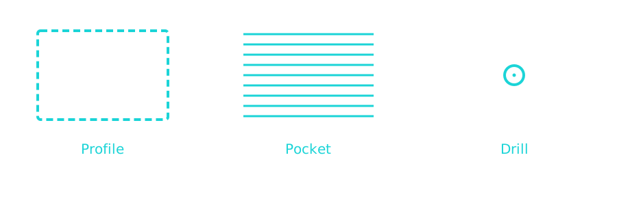
Three Toolpath Types
Profile
Cuts along a drawn outline — the toolpath you'll use to cut a panel free from stock.
The Bit Has a Diameter
It's not a mathematical line — it's a spinning cylinder with real width.
Cut exactly on your drawn line, and the bit removes material on both sides of it.
Profile Offset
Cutting a Part: Use Outside
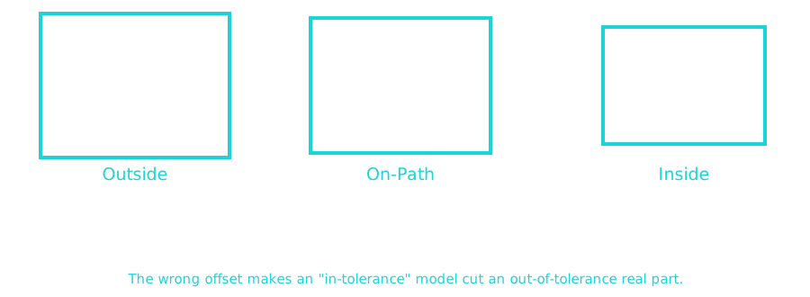
The bit runs outside your line, so the material it removes is all waste — your part comes out full size.
Cutting a Hole: Use Inside
The bit runs inside your line, so the hole ends up exactly the size you drew — not slightly small.
This Is a Tolerance Problem
The wrong offset choice makes a perfectly modeled, in-tolerance part come out of the machine the wrong size.
Same idea as Unit 1 Session 9 — a spec on a screen doesn't guarantee a correct real part.
Two Things to Remember
Ask "am I keeping this or removing it?" before choosing an offset.
That question alone tells you Outside or Inside almost every time.
Two Things to Remember
On-Path is rarely what you actually want.
It ignores the bit's width entirely — both a cut part and a cut hole come out wrong-sized.
Next Time
Session 8: Pockets, Step-Over & Step-Down
Clearing out material instead of just cutting along a line.
'F' → Fullscreen
Build
Step 1: Identify Toolpath Type
For each of the following, name which toolpath type (Profile, Pocket, or Drill) you'd use:
- Cutting a rectangular panel free from a full sheet
- Clearing a recessed tray area into a panel's face
- A mounting hole for a bolt
Step 2: Choose the Right Offset
For each scenario, decide Outside, Inside, or On-Path, and justify using the "am I keeping this or removing it?" question:
- Cutting your control panel's outer shape free from a sheet
- Cutting a joystick's mounting hole to its exact drawn size
- A test cut where dimensional accuracy genuinely doesn't matter
Step 3: Predict the Error
If you accidentally used Inside offset instead of Outside when cutting a part free from stock, would the part come out too big or too small? Explain using the bit-diameter idea from today.
Checkpoint
Before you move on, confirm you can answer this out loud, in your own words:
Why does the same drawn line need a different offset depending on whether you're cutting a part out or cutting a hole into it?
Reflection
Answer the following questions before submitting your work.
- Which offset choice do you think would be easiest to get backward by accident — Outside, Inside, or On-Path? Why?
- How is today's offset problem similar to Unit 1's tolerance work, even though the vocabulary is different?
- Session 8 covers pockets. Based on today, what do you expect is different about programming a pocket compared to a profile cut?
Submit
Submit your toolpath identifications, your offset choices with justifications, your error prediction, and your reflection.