Activity 2.2: Reading Circuits
Electronics Primer — Day 2 of 3

Activity 2.2
Reading Circuits
Key Concepts
Schematic Symbols
Breadboards
Resistors & LEDs
Why Read a Diagram?
A schematic describes a circuit using symbols instead of a photo — the same way sheet music describes a song instead of a recording. Anyone who knows the symbols can build the exact same circuit from one.
Common Schematic Symbols

Five symbols you'll see constantly: a power source, a resistor, an LED, a switch, and ground.
The Breadboard: Rows and Rails
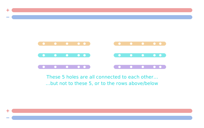
Under the plastic, short rows of holes are electrically connected to each other — but not to the row next to them. The long outer rails run the full length of the board, for power and ground.
Plugging two things into the same short row connects them. Plugging them into different rows doesn't — even if they look close together.
Resistors: What They Actually Do
A resistor limits how much current flows through part of a circuit — mainly, protecting other components (like an LED) from more current than they can safely handle.
Resistors are often marked with color bands instead of printed numbers. You won't need to memorize the color code for this course — we'll always tell you the value you need — but it's worth knowing that's why a resistor has stripes on it.
LEDs: Polarity Matters
An LED only lets current flow one direction. The longer leg is the anode(positive side); the shorter leg is the cathode (negative side). Wire it backwards, and it simply won't light — it won't damage anything.
Today's Circuit

A single LED and resistor, wired directly across the RedBoard's 3.3V and GND pins — no code today. If it's wired correctly, it lights up the instant you connect it.
Today's Objectives
- Reading a schematic's power source, resistor, LED, switch, and ground symbols
- Explaining how a breadboard's rows and rails connect internally
- Building a working LED circuit directly from a schematic
Key Terms
- Schematic
- A diagram describing a circuit using standardized symbols.
- Breadboard
- A reusable prototyping board whose short rows (and long outer rails) connect groups of holes electrically.
- Resistor
- A component that limits current flow, often to protect other components.
- Anode / Cathode
- The positive (anode, longer leg) and negative (cathode, shorter leg) sides of an LED.
- Ground (GND)
- The circuit's reference point, where current returns to complete the loop.
'F' → Fullscreen
Build
Today's build uses no code — just the schematic, your breadboard, and the RedBoard's fixed 3.3V and GND pins.
Task 1: Read the Schematic
- Identify each symbol in today's circuit diagram: power source, resistor, LED, and ground.
- Label which leg of the LED is the anode and which is the cathode.
Task 2: Build the Circuit
- Wire the LED and resistor in series on your breadboard, matching the schematic.
- Connect the circuit to the RedBoard's 3.3V and GND pins. If everything's correct, the LED lights up immediately — no code required.
Finding those two pins: the board abbreviates its labels, so the 3.3V pin is printed 3V3 — not "3.3V". Both it and GND are on the bottom header.
Task 3: Reverse the LED
- Flip the LED around in the breadboard and observe what happens.
- Flip it back to the correct orientation before moving on.
Checkpoint
Your LED should be glowing steadily. If it's not:
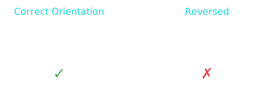
- Check the LED's orientation — flip it around
- Check the resistor is actually in the circuit, in series with the LED
- Check both ends of every wire are fully seated in the breadboard
Reflection
Answer the following questions before submitting your work.
- What does each symbol in today's schematic represent: the power source, the resistor, the LED, and ground?
- Why did the LED need a specific orientation, and what happened when you reversed it?
- What do you predict would happen to the LED if the resistor were removed entirely? Don't actually try it — just explain your reasoning.
Submit
Submit the required files to the appropriate dropbox.