Activity 2.3: Ohm's Law and Meet the Microcontroller
Electronics Primer — Day 3 of 3

Activity 2.3
Ohm's Law and Meet the Microcontroller
Key Concepts
Ohm's Law
GPIO Pins
Objects & Pin()
Yesterday's Circuit, One Question
Why 330Ω, specifically? Would a different resistor have worked? Today's math answers that.
Ohm's Law
Voltage, current, and resistance aren't independent — they're locked together by one equation:
V = I × R
Voltage (volts) = Current (amps) × Resistance (ohms)
Rearranging the Formula
Same equation, solved for a different variable:
I = V ÷ R — solve for current
R = V ÷ I — solve for resistance
Worked Example: Checking Yesterday's Resistor
3.3V source, 330Ω resistor. How much current flows?
I = V ÷ R = 3.3 ÷ 330 = 0.01A (10mA)
That's a safe, small current for an LED — which is exactly why 330Ω gets picked so often, not because it's the only option.
Meet the RedBoard RP2350
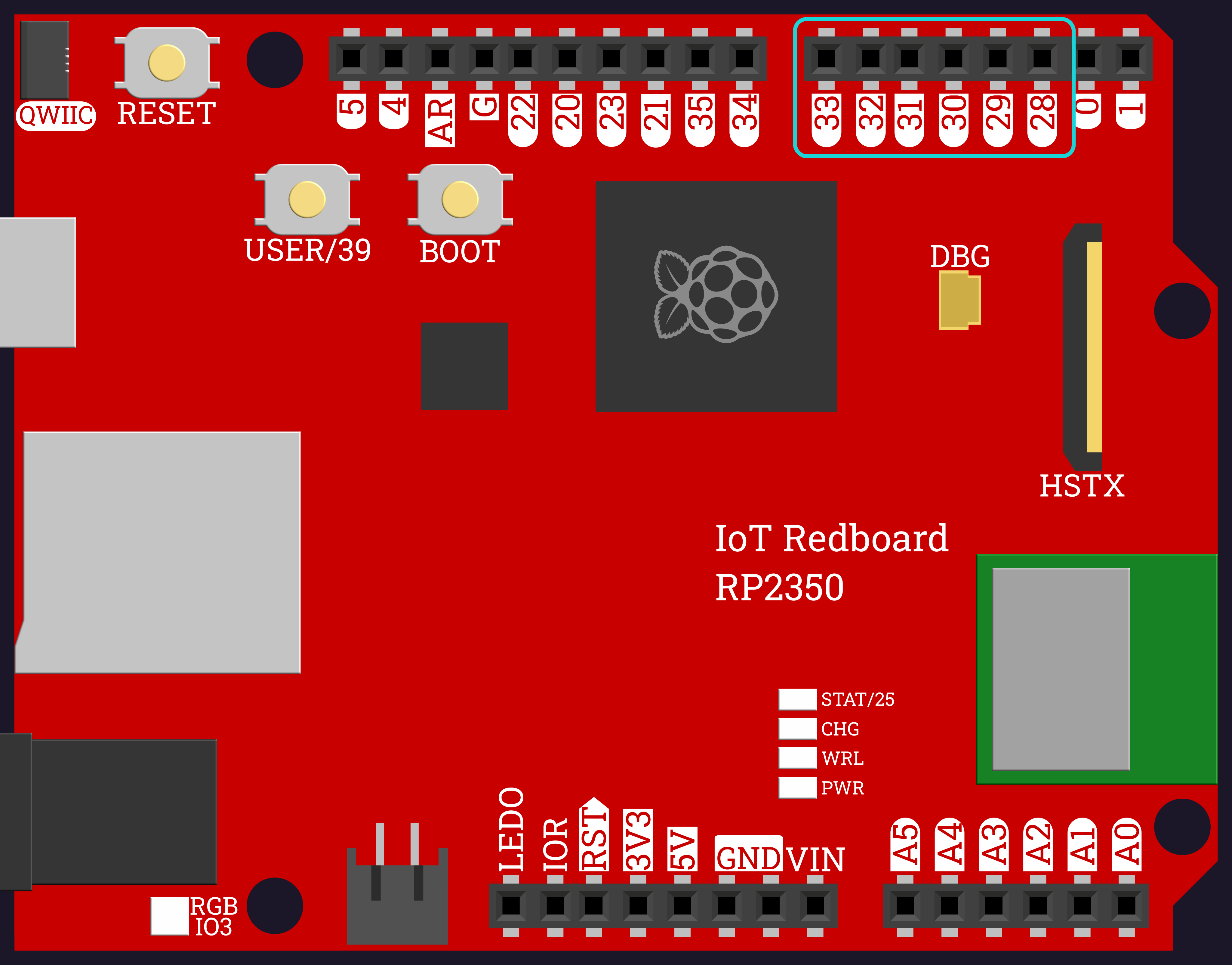
The board you'll use the rest of this unit. Its GPIO pins (General Purpose Input/Output) can be controlled entirely by code. The six outlined above are the ones you'll wire to.
Digital Pins: On or Off
A digital pin has exactly two states: HIGH(on, about 3.3V) or LOW (off, 0V). No in-between — that comes later, with analog pins.
Meet Your First Object
from machine import Pin
led = Pin(28, Pin.OUT)led.value(1)
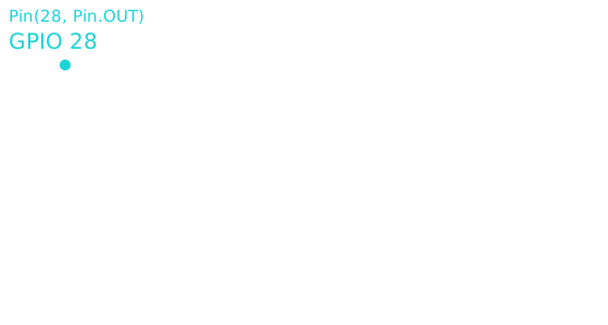
Pin(28, Pin.OUT) creates an object — something that bundles together information (which pin, which direction) and actions you can perform on it. led.value(1) calls one of those actions, called a method, using a dot.
Today's Objectives
- Calculating voltage, current, or resistance with Ohm's Law
- Explaining what a GPIO pin is and its two digital states
- Writing your first line of code to control a real LED
Key Terms
- Ohm's Law
- The relationship V = I × R between voltage, current, and resistance.
- GPIO
- General Purpose Input/Output — a microcontroller pin that code can control.
- Digital Pin
- A pin with exactly two states: HIGH (on) or LOW (off).
- Object
- Something that bundles data and actions together — like a Pin, which knows its number and direction, and has actions you can call on it.
- Method
- An action you call on an object using dot notation, like
led.value(1).
'F' → Fullscreen
Build
Task 1: Ohm's Law Practice
- A circuit has 3.3V across a 330Ω resistor. What's the current?
- A circuit has 3.3V, and you want exactly 3.3mA (0.0033A) of current. What resistance do you need?
- A circuit has a 220Ω resistor with 10mA (0.01A) flowing through it. What's the voltage?
Task 2: Rewire to a GPIO Pin
- Move your LED and resistor from yesterday's fixed 3.3V pin to GPIO 28, keeping GND the same.
- The LED should now be off — a GPIO pin starts LOW until code says otherwise.
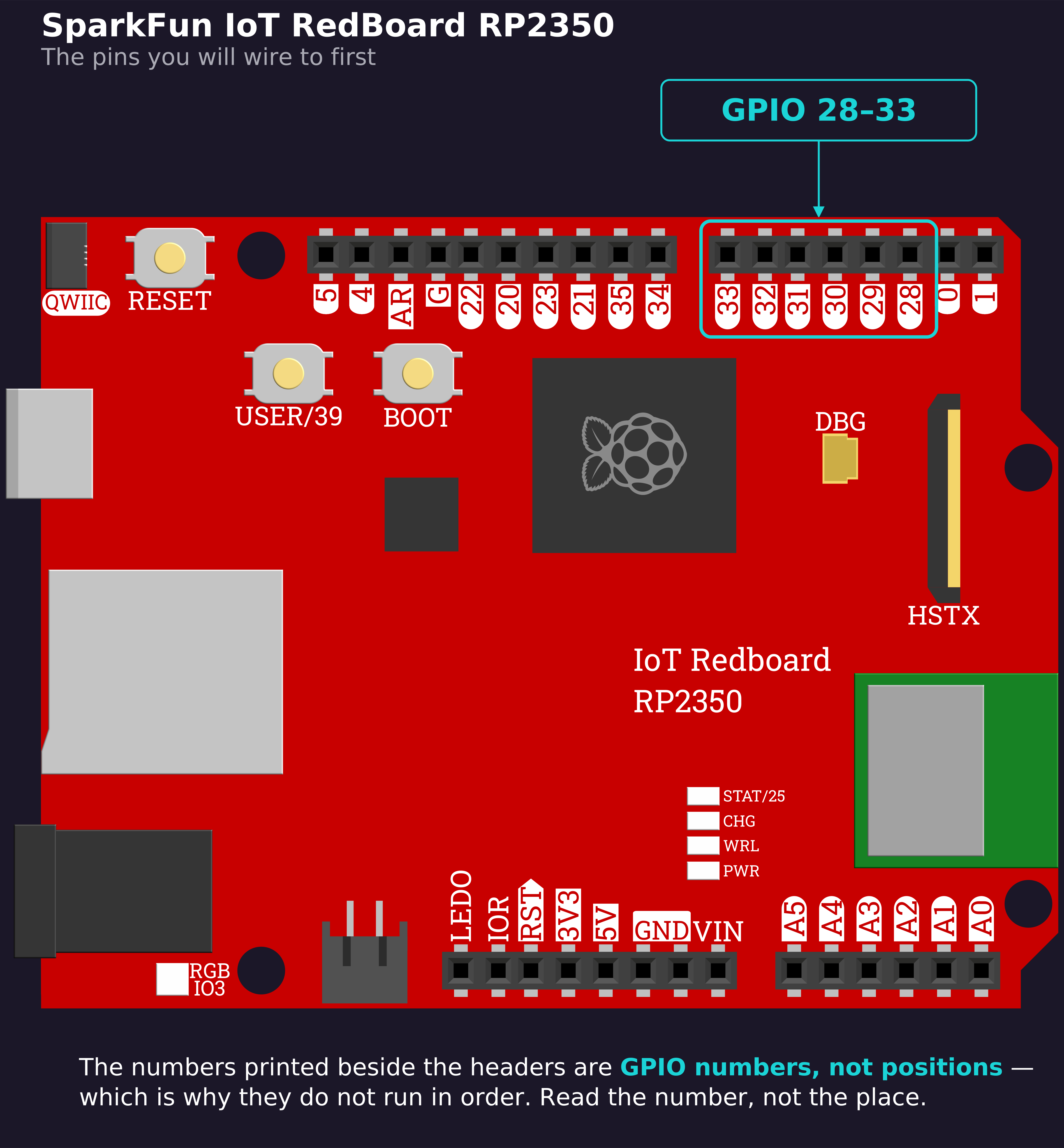
Finding GPIO 28 on the board: look along the block of eight pins on the top header for the one marked 28 — its neighbors are 29 on one side and 0/TXD on the other. Keep this card handy; you will be hunting for pins all unit.
Task 3: Your First Code
- Create a new MicroPython program named 2-3-first-blink.
- Import
Pin, create aPinobject for GPIO 28 set as output, and turn it on.
from machine import Pin
led = Pin(28, Pin.OUT)led.value(1)Task 4: Turn It Off (and Blink Once)
- Import
time, wait one second after turning the LED on, then turn it off.
from machine import Pinimport time
led = Pin(28, Pin.OUT)led.value(1)time.sleep(1)led.value(0)Checkpoint
When you run your script, the LED should:
- Turn on immediately
- Stay on for about one second
- Turn off, and the script should end
Reflection
Answer the following questions before submitting your work.
- Walk through the math: given a 3.3V source and a 330Ω resistor, what's the current, and how did you calculate it?
- In
led = Pin(28, Pin.OUT), what isled, and what does callingled.value(1)actually do? - Why did you move the LED from the 3.3V/GND rail to a GPIO pin before writing any code — what did that change make possible?
Submit
Submit the required files to the appropriate dropbox.